Unity AI Development: An xNode-based Graphical FSM Tutorial
Take your Unity AI game to the next level with xNode. In this tutorial, we boost our FSM-based AI with a graphical user interface, delivering an enhanced development environment.

Take your Unity AI game to the next level with xNode. In this tutorial, we boost our FSM-based AI with a graphical user interface, delivering an enhanced development environment.

Garegin is an accomplished Unity and C# game developer. He created a networking protocol for gamified playground equipment, served as the CTO of an educational gaming startup, and was a game developer on a multinational social-casino team.
PREVIOUSLY AT

In “Unity AI Development: A Finite-state Machine Tutorial,” we created a simple stealth game—a modular FSM-based AI. In the game, an enemy agent patrols the gamespace. When it spots the player, the enemy changes its state and follows the player instead of patrolling.
In this second leg of our Unity journey, we will build a graphical user interface (GUI) to create the core components of our finite-state machine (FSM) more rapidly, and with an improved developer experience.
Let’s Refresh
The FSM detailed in the previous tutorial was built of architectural blocks as C# scripts. We added custom ScriptableObject actions and decisions as classes. Our ScriptableObject approach allowed us to have an easily maintainable and customizable FSM. In this tutorial, we replace our FSM’s drag-and-drop ScriptableObjects with a graphical option.
In your game, if you’d like for the player to win more easily, replace the player detection script with this updated script that narrows the enemy’s field of vision.
Getting Started With xNode
We’ll build our graphical editor using xNode, a framework for node-based behavior trees that will display our FSM’s flow visually. Although Unity’s GraphView can accomplish the job, its API is both experimental and meagerly documented. xNode’s user interface delivers a superior developer experience, facilitating the prototyping and rapid expansion of our FSM.
Let’s add xNode to our project as a Git dependency using the Unity Package Manager:
- In Unity, click Window > Package Manager to launch the Package Manager window.
- Click + (the plus sign) at the window’s top-left corner and select Add package from git URL to display a text field.
- Type or paste
https://github.com/siccity/xNode.gitin the unlabeled text box and click the Add button.
Now we’re ready to dive deep and understand the key components of xNode:
Node class | Represents a node, a graph's most fundamental unit. In this xNode tutorial, we derive from the Node class new classes that declare nodes equipped with custom functionality and roles. |
NodeGraph class | Represents a collection of nodes (Node class instances) and the edges that connect them. In this xNode tutorial, we derive from NodeGraph a new class that manipulates and evaluates the nodes. |
NodePort class | Represents a communication gate, a port of type input or type output, located between Node instances in a NodeGraph. The NodePort class is unique to xNode. |
[Input] attribute | The addition of the [Input] attribute to a port designates it as an input, enabling the port to pass values to the node it is part of. Think of the [Input] attribute as a function parameter. |
[Output] attribute | The addition of the [Output] attribute to a port designates it as an output, enabling the port to pass values from the node it is part of. Think of the [Output] attribute as the return value of a function. |
Visualizing the xNode Building Environment
In xNode, we work with graphs where each State and Transition takes the form of a node. Input and/or output connection(s) enable the node to relate to any or all other nodes in our graph.
Let’s imagine a node with three input values: two arbitrary and one boolean. The node will output one of the two arbitrary-type input values, depending on whether the boolean input is true or false.

Branch NodeTo convert our existing FSM to a graph, we modify the State and Transition classes to inherit the Node class instead of the ScriptableObject class. We create a graph object of type NodeGraph to contain all of our State and Transition objects.
Modifying BaseStateMachine to Use As a Base Type
We’ll begin building our graphical interface by adding two new virtual methods to our existing BaseStateMachine class:
Init | Assigns the initial state to the CurrentState property |
Execute | Executes the current state |
Declaring these methods as virtual allows us to override them, so we can define the custom behaviors of classes inheriting the BaseStateMachine class for initialization and execution:
using System;
using System.Collections.Generic;
using UnityEngine;

namespace Demo.FSM
{
    public class BaseStateMachine : MonoBehaviour
    {
        [SerializeField] private BaseState _initialState;
        private Dictionary<Type, Component> _cachedComponents;
        private void Awake()
        {
            Init();
            _cachedComponents = new Dictionary<Type, Component>();
        }

        public BaseState CurrentState { get; set; }

        private void Update()
        {
            Execute();
        }

        public virtual void Init()
        {
            CurrentState = _initialState;
        }

        public virtual void Execute()
        {
            CurrentState.Execute(this);
        }

       // Allows us to execute consecutive calls of GetComponent in O(1) time
        public new T GetComponent<T>() where T : Component
        {
            if(_cachedComponents.ContainsKey(typeof(T)))
                return _cachedComponents[typeof(T)] as T;

            var component = base.GetComponent<T>();
            if(component != null)
            {
                _cachedComponents.Add(typeof(T), component);
            }
            return component;
        }

    }
}
Next, under our FSM folder, let’s create:
FSMGraph | A folder |
BaseStateMachineGraph | A C# class within FSMGraph
|
For the time being, BaseStateMachineGraph will inherit just the BaseStateMachine class:
using UnityEngine;

namespace Demo.FSM.Graph
{
    public class BaseStateMachineGraph : BaseStateMachine
    {
    }
}
We can’t add functionality to BaseStateMachineGraph until we create our base node type; let’s do that next.
Implementing NodeGraph and Creating a Base Node Type
Under our newly created FSMGraph folder, we’ll create:
FSMGraph | A class |
For now, FSMGraph will inherit just the NodeGraph class (with no added functionality):
using UnityEngine;
using XNode;

namespace Demo.FSM.Graph
{
    [CreateAssetMenu(menuName = "FSM/FSM Graph")]
    public class FSMGraph : NodeGraph
    {
    }
}
Before we create classes for our nodes, let’s add:
FSMNodeBase | A class to be used as a base class by all of our nodes |
The FSMNodeBase class will contain an input named Entry of type FSMNodeBase to enable us to connect nodes to one another.
We will also add two helper functions:
GetFirst | Retrieves the first node connected to the requested output |
GetAllOnPort | Retrieves all remaining nodes that connect to the requested output |
using System.Collections.Generic;
using XNode;

namespace Demo.FSM.Graph
{
    public abstract class FSMNodeBase : Node
    {
        [Input(backingValue = ShowBackingValue.Never)] public FSMNodeBase Entry;

        protected IEnumerable<T> GetAllOnPort<T>(string fieldName) where T : FSMNodeBase
        {
            NodePort port = GetOutputPort(fieldName);
            for (var portIndex = 0; portIndex < port.ConnectionCount; portIndex++)
            {
                yield return port.GetConnection(portIndex).node as T;
            }
        }

        protected T GetFirst<T>(string fieldName) where T : FSMNodeBase
        {
            NodePort port = GetOutputPort(fieldName);
            if (port.ConnectionCount > 0)
                return port.GetConnection(0).node as T;
            return null;
        }
    }
}
Ultimately, we’ll have two types of state nodes; let’s add a class to support these:
BaseStateNode | A base class to support both StateNode and RemainInStateNode
|
namespace Demo.FSM.Graph
{
    public abstract class BaseStateNode : FSMNodeBase
    {
    }
}
Next, modify the BaseStateMachineGraph class:
using UnityEngine;
namespace Demo.FSM.Graph
{
    public class BaseStateMachineGraph : BaseStateMachine
    {
        public new BaseStateNode CurrentState { get; set; }
    }
}
Here, we’ve hidden the CurrentState property inherited from the base class and changed its type from BaseState to BaseStateNode.
Creating Building Blocks for Our FSM Graph
Now, to form our FSM’s main building blocks, let’s add three new classes to our FSMGraph folder:
StateNode | Represents the state of an agent. On execute, StateNode iterates over the TransitionNodes connected to the output port of the StateNode (retrieved by a helper method). StateNode queries each one whether to transition the node to a different state or leave the node's state as is. |
RemainInStateNode | Indicates a node should remain in the current state. |
TransitionNode | Makes the decision to transition to a different state or stay in the same state. |
In the previous Unity FSM tutorial, the State class iterates over the transitions list. Here in xNode, StateNode serves as State’s equivalent to iterate over the nodes retrieved via our GetAllOnPort helper method.
Now add an [Output] attribute to the outgoing connections (the transition nodes) to indicate that they should be part of the GUI. By xNode’s design, the attribute’s value originates in the source node: the node containing the field marked with the [Output] attribute. As we are using [Output] and [Input] attributes to describe relationships and connections that will be set by the xNode GUI, we can’t treat these values as we normally would. Consider how we iterate through Actions versus Transitions:
using System.Collections.Generic;
namespace Demo.FSM.Graph
{
    [CreateNodeMenu("State")]
    public sealed class StateNode : BaseStateNode
    {
        public List<FSMAction> Actions;
        [Output] public List<TransitionNode> Transitions;
        public void Execute(BaseStateMachineGraph baseStateMachine)
        {
            foreach (var action in Actions)
                action.Execute(baseStateMachine);
            foreach (var transition in GetAllOnPort<TransitionNode>(nameof(Transitions)))
                transition.Execute(baseStateMachine);
        }
    }
}
In this case, the Transitions output can have multiple nodes attached to it; we have to call the GetAllOnPort helper method to obtain a list of the [Output] connections.
RemainInStateNode is, by far, our simplest class. Executing no logic, RemainInStateNode merely indicates to our agent—in our game’s case, the enemy—to remain in its current state:
namespace Demo.FSM.Graph
{
    [CreateNodeMenu("Remain In State")]
    public sealed class RemainInStateNode : BaseStateNode
    {
    }
}
At this point, the TransitionNode class is still incomplete and will not compile. The associated errors will clear once we update the class.
To build TransitionNode, we need to get around xNode’s requirement that the value of the output originates in the source node—as we did when we built StateNode. A major difference between StateNode and TransitionNode is that TransitionsNode’s output may attach to only one node. In our case, GetFirst will fetch the one node attached to each of our ports (one state node to transition to in the true case and another to transition to in the false case):
namespace Demo.FSM.Graph
{
    [CreateNodeMenu("Transition")]
    public sealed class TransitionNode : FSMNodeBase
    {
        public Decision Decision;
        [Output] public BaseStateNode TrueState;
        [Output] public BaseStateNode FalseState;
        public void Execute(BaseStateMachineGraph stateMachine)
        {
            var trueState = GetFirst<BaseStateNode>(nameof(TrueState));
            var falseState = GetFirst<BaseStateNode>(nameof(FalseState));
            var decision = Decision.Decide(stateMachine);
            if (decision && !(trueState is RemainInStateNode))
            {
                stateMachine.CurrentState = trueState;
            }
            else if(!decision && !(falseState is RemainInStateNode))
                stateMachine.CurrentState = falseState;
        }
    }
}
Let’s have a look at the graphical results from our code.
Creating the Visual Graph
Now, with all the FSM classes sorted out, we can proceed to create our FSM Graph for the game’s enemy agent. In the Unity project window, right-click the EnemyAI folder and choose: Create > FSM > FSM Graph. To make our graph easier to identify, let’s rename it EnemyGraph.
In the xNode Graph editor window, right-click to reveal a drop-down menu listing State, Transition, and RemainInState. If the window is not visible, double-click the EnemyGraph file to launch the xNode Graph editor window.
-
To create the
ChaseandPatrolstates:-
Right-click and choose State to create a new node.
-
Name the node
Chase. -
Return to the drop-down menu, choose State again to create a second node.
-
Name the node
Patrol. -
Drag and drop the existing
ChaseandPatrolactions to their newly created corresponding states.
-
-
To create the transition:
-
Right-click and choose Transition to create a new node.
-
Assign the
LineOfSightDecisionobject to the transition’sDecisionfield.
-
-
To create the
RemainInStatenode:- Right-click and choose RemainInState to create a new node.
-
To connect the graph:
-
Connect the
Patrolnode’sTransitionsoutput to theTransitionnode’sEntryinput. -
Connect the
Transitionnode’sTrue Stateoutput to theChasenode’sEntryinput. -
Connect the
Transitionnode’sFalse Stateoutput to theRemain In Statenode’sEntryinput.
-
The graph should look like this:

Nothing in the graph indicates which node—the Patrol or Chase state—is our initial node. The BaseStateMachineGraph class detects four nodes but, with no indicators present, cannot choose the initial state.
To resolve this issue, let’s create:
FSMInitialNode | A class whose single output of type StateNode is named InitialNode
|
Our output InitialNode denotes the initial state. Next, in FSMInitialNode, create:
NextNode | A property to enable us to fetch the node connected to the InitialNode output |
using XNode;
namespace Demo.FSM.Graph
{
    [CreateNodeMenu("Initial Node"), NodeTint("#00ff52")]
    public class FSMInitialNode : Node
    {
        [Output] public StateNode InitialNode;
        public StateNode NextNode
        {
            get
            {
                var port = GetOutputPort("InitialNode");
                if (port == null || port.ConnectionCount == 0)
                    return null;
                return port.GetConnection(0).node as StateNode;
            }
        }
    }
}
Now that we created theFSMInitialNode class, we can connect it to the Entry input of the initial state and return the initial state via the NextNode property.
Let’s go back to our graph and add the initial node. In the xNode editor window:
- Right-click and choose Initial Node to create a new node.
- Attach FSM Node’s output to the
Patrolnode’sEntryinput.
The graph should now look like this:

To make our lives easier, we’ll add to FSMGraph:
InitialState | A property |
The first time we try to retrieve the InitialState property’s value, the getter of the property will traverse all nodes in our graph as it tries to find FSMInitialNode. Once FSMInitialNode is located, we use the NextNode property to find our initial state node:
using System.Linq;
using UnityEngine;
using XNode;
namespace Demo.FSM.Graph
{
    [CreateAssetMenu(menuName = "FSM/FSM Graph")]
    public sealed class FSMGraph : NodeGraph
    {
        private StateNode _initialState;
        public StateNode InitialState
        {
            get
            {
                if (_initialState == null)
                    _initialState = FindInitialStateNode();
                return _initialState;
            }
        }
        private StateNode FindInitialStateNode()
        {
            var initialNode = nodes.FirstOrDefault(x => x is FSMInitialNode);
            if (initialNode != null)
            {
                return (initialNode as FSMInitialNode).NextNode;
            }
            return null;
        }
    }
}
Now, in our BaseStateMachineGraph, let’s reference FSMGraph and override our BaseStateMachine’s Init and Execute methods. Overriding Init sets CurrentState as the graph’s initial state, and overriding Execute calls Execute on CurrentState:
using UnityEngine;
namespace Demo.FSM.Graph
{
    public class BaseStateMachineGraph : BaseStateMachine
    {
        [SerializeField] private FSMGraph _graph;
        public new BaseStateNode CurrentState { get; set; }
        public override void Init()
        {
            CurrentState = _graph.InitialState;
        }
        public override void Execute()
        {
            ((StateNode)CurrentState).Execute(this);
        }
    }
}
Now, let’s apply our graph to our Enemy object, and see it in action.
Testing the FSM Graph
In preparation for testing, in the Unity Editor’s Project window, we need to:
-
Open the SampleScene asset.
-
Locate our
Enemygame object in the Unity hierarchy window. -
Replace the
BaseStateMachinecomponent with theBaseStateMachineGraphcomponent:-
Click Add Component and select the correct
BaseStateMachineGraphscript. -
Assign our FSM graph,
EnemyGraph, to theGraphfield of theBaseStateMachineGraphcomponent. -
Delete the
BaseStateMachinecomponent (as it is no longer needed) by right-clicking and selecting Remove Component.
-
Now the Enemy game object should look like this:
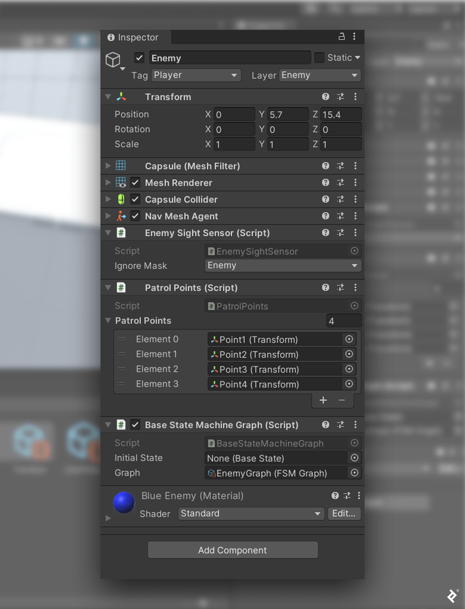
Enemy Game ObjectThat’s it! Now we have a modular FSM with a graphic editor. When we click the Play button, we see our graphically created enemy AI works exactly as our previously created ScriptableObject enemy.
Forging Ahead: Optimizing Our FSM
The advantages of using a graphical editor are self-evident, but I’ll leave you with a word of caution: As you develop more sophisticated AI for your game, the number of states and transitions grows, and the FSM becomes confusing and difficult to read. The graphical editor grows to resemble a web of lines that originate in multiple states and terminate at multiple transitions—and vice versa, making our FSM difficult to debug.
As we did in the previous tutorial, we invite you to make the code your own, and leave the door open for you to optimize your stealth game and address these concerns. Imagine how helpful it would be to color-code your state nodes to indicate whether a node is active or inactive, or resize the RemainInState and Initial nodes to limit their screen real estate.
Such enhancements are not merely cosmetic. Color and size references would help us identify where and when to debug. A graph that is easy on the eye is also simpler to assess, analyze, and comprehend. Any next steps are up to you—with the foundation of our graphical editor in place, there’s no limit to the developer experience improvements you can make.
The editorial team of the Toptal Engineering Blog extends its gratitude to Goran Lalić and Maddie Douglas for reviewing the code samples and other technical content presented in this article.
Understanding the basics
Why do we use finite-state machines?
A finite-state machine (FSM) is a computational model that can be in just one state at a given time. Accordingly, we can represent any system requiring such functionality (e.g., to manage traffic lights or elevators) as an FSM. We can also use an FSM to develop game AI and game management systems.
Is artificial intelligence an application of FSM?
Adding AI is one way to implement an FSM. In the case of an FSM, AI takes the form of coded classes and custom actions, decisions, and behaviors.
Are FSMs graphs?
FSMs can be represented as graphs. In a theoretical sense, graphs are vertices and edges. In the case of an xNode FSM, vertices represent states and transitions, while edges represent transition flows.
Why is an FSM useful?
An FSM can be used to simulate sequential logic.
Garegin Tadevosyan
Yerevan, Armenia
Member since July 1, 2021
About the author
Garegin is an accomplished Unity and C# game developer. He created a networking protocol for gamified playground equipment, served as the CTO of an educational gaming startup, and was a game developer on a multinational social-casino team.
PREVIOUSLY AT