A Software Defined Radio Tutorial: Images From the International Space Station and Listening to Hams With an RTL-SDR
Radio has used fundamentally the same technology since Marconi’s experiments in 1895. However, improved circuit design and signal processing techniques have allowed us to transmit much more and much farther out than before.
In this article, with a laptop and less than $30 worth of equipment, we’ll capture images transmitted from the International Space Station and listen to amateur radio conversations at a local repeater.
Amin is a Ruby Association certified Gold Ruby Programmer who is passionate about learning new applications for technology.
Expertise
Radio is the transmission and receiving of electromagnetic radiation with wavelengths longer than that of infrared light. You’re forgiven if that definition didn’t make sense, though, and until a few years ago, it wouldn’t have to me either. Radio technology powers almost all wireless connectivity around us: Bluetooth, WiFi, 3G, 4G, and your microwave oven—all these operate on radio principles. The technology is over a hundred years old, and yet I realized that I knew very little about it.
So, I decided to start learning and reached out to my national amateur radio association, the Pakistan Amateur Radio Society (PARS), a member of the International Amateur Radio Union (IARU), which in turn represents amateur radio to the International Telecommunication Union (ITU), the UN agency whose job it is to coordinate telecommunication operations and services worldwide. PARS runs a few radio repeaters across the country, and one of them was in Lahore, where I live.
While radio has used fundamentally the same technology since Guglielmo Marconi first conducted his experiments in 1895, improved circuit design and signal processing techniques have allowed us to transmit much more and much farther out than before. Now, it’s possible for someone with a laptop and less than $30 worth of equipment to receive a wide range of radio frequencies, and we’ll be doing just that.
In this software-defined radio tutorial, I’ll set up a software-defined radio device (SDR) and an antenna, and listen to a conversation between two licensed ham radio operators via the Lahore repeater. I will then use the same equipment to receive an image transmitted from the International Space Station, a spacecraft orbiting the Earth, and use it to claim the ARISS SSTV Award, demonstrating how easy it is to browse the radio spectrum with cheap equipment and be recognized. Through the hardware used in this article, you can only receive radio transmissions and not transmit your own own, but that is fine since you need an amateur radio license before doing so, anyways.
Caution! It is very easy to perform an illegal activity with radio equipment, which is why this article will continuously caution you and cite the law. The author lives in and conducted these experiments legally in Pakistan. While federal radio laws in Pakistan are severely restrictive, your jurisdiction may be more so. In 2019, a United Nations expert was arrested in Tunisia for possessing the same software-defined radio device we will be using. It is your responsibility to ensure that you comply with local laws when performing radio experiments. Please note, though: I am not a lawyer, and this does not constitute legal advice. You must consult your own lawyer for clarification.
If you live in Pakistan, you must obtain a PARS shortwave listening (SWL) membership before you obtain a radio receiver. Pakistan’s Wireless Telegraphy Act, 1933 prohibits possession of wireless telegraphy apparatus; however, SWL members are allowed to possess receivers. Reach out to me for a PARS reference letter, if you’re looking to become a member.
Setting Up Our Dipole Antenna and SDR Receiver
“What even is a ‘software-defined’ radio?” I hear you ask!
A software-defined radio, is a radio device where most of the electrical components “emulated” in software. Before the rise of SDRs, you would need a dedicated circuit to perform the task of processing the signals to and from the radio. Things like signal filtering, frequency mixing, radio wave detection, signal amplification, modulation/demodulation, and others were done with dedicated circuits. However, since computers have become faster, we can perform these functions in software instead, making these types of radios software-defined.
A popular (and cheap) SDR receiver is Digital Video Broadcast (DVB-T) receiver with the Realtek RTL2832U controller and tuner integrated circuit. While their original purpose was to receive video, these are now repurposed to receive radio signals, and have come to be known as RTL-SDR devices. I’ll be using the RTL-SDR receiver and dipole from RTL-SDR.com. It currently costs $29.95, ships worldwide, comes with a temperature compensated oscillator (TCXO), and a bias tee, which are great to have, but beyond the scope of this article to discuss. It also comes with an adjustable dipole antenna kit, letting you listen from ~70 MHz to ~1030 MHz signals.
Day 2 of ARISS Int'l F2F:
— ARISS (@ARISS_status) June 27, 2019
David Honess of ESA opens today's sessions proposing excellent ways to engage kids with ISS ham radio projects using Raspberry Pi, RTL-SDR, SSTV mode communications, etc. through an online linkup with our F2F meeting in Montreal. pic.twitter.com/Mp25cljrAH
The RTL-SDR dipole kit I’m using was also recommended by representatives of the European Space Agency at the Amateur Radio in Space (ARISS) International Face-to-face Meeting in June, 2019.
Setting up the antenna is easy. Screw the long prongs of the antenna into the center, mount it on a window with the provided suction cup, and open the dipole arms at exactly 49.65 cm (1 foot 7.55 inches) each. Connect the female end of the provided longer cable to the dipole’s male end, the male end of the longer cable to your SDR, and then mount the antenna vertically as high as possible outside. Preferably on a window, using the provided suction cup mount. Here’s a picture of how it should look:
Finally, screw the dangling end of the long cable into your SDR, and plug your SDR into your computer’s USB port. At this point, you can go with any number of SDR applications, but since I’m on MacOS, where options are limited, I’ll use CubicSDR.
brew cask install cubicsdr
Upon opening CubicSDR, you’ll be presented with a dialogue box to select your SDR and its settings. Choose the Generic RTL2832U OEM like I’ve chosen in the image, and change the sample rate to 2.048MHz
)
When CubicSDR starts, you can start browsing the spectrum immediately. I recommend starting with familiar FM radio broadcasts. Here’s a video of me browsing the local radio stations as they are available to me in Lahore.
Next up, we listen to two amateur radio operators on the Lahore, repeater, but before we start, let’s discuss what amateur radio even is.
What Is Amateur Radio?
“Okay, but what is ‘amateur’ radio?” I hear you ask this time!
Amateur radio is the use of the radio spectrum by licensed operators for non-commercial activities. These may include communication, training, experimentation, contesting, or more. Every jurisdiction may have their own legal definition as well. Amateur radio operators are restricted to using the frequencies dedicated to the amateur service.
“Amateur Service” means a radio communication service for the purpose of self-training, intercommunication and technical investigations carried out by amateurs, that is, by persons duly authorized under these Regulations interested in radio technique solely with a personal aim and without pecuniary interest; – Amateur Radio Services Regulations, 2004, Pakistan
With that settled, let’s look at what our local amateur radio frequencies are. They’re published along with the definitions of everything by the Pakistani Frequency Allocation Board, in a document called the Pakistan Table of Frequency Allocations. I maintain a a gist of them all for easy reference, but here are the very high frequency (VHF) bands:
| Unit | Frequency range | ITU – Region 3 | Pakistan's allocations |
|---|---|---|---|
| MHz | 144 – 146 | AMATEUR AMATEUR-SATELLITE 5.216 | AMATEUR AMATEUR-SATELLITE |
| MHz | 146 – 148 | AMATEUR FIXED MOBILE 5.217 | AMATEUR FIXED MOBILE |
That said, here’s an important note on legalities: The RTL-SDR, and this setup, is incredibly powerful. Even though you only have access to a small portion of Pakistan’s (or your local) designated amateur ranges, which usually span from 1,800 KHz to 250 GHz, there are other services operating on the spectrum. You should be aware of what services you can, or more importantly can’t listen to: In Pakistan, as is in the UK, you can not listen to any transmissions not intended for you, nor intended to be open to the public, doing so may carry a fine or a prison sentence in Pakistan according to the Pakistan Telecommunication (Re-organization) Act, 1996, and the Prevention of Electronic Crime Act, 2016. Regardless, it is entirely your responsibility to look up local laws. In the US, what transmissions you can listen to depend on your local jurisdiction.
Listening to Amateur Radio Operators on the Lahore Repeater
“You want me to ask what a repeater is, don’t you?” you ask. And I’m glad you asked.
When radio devices talk to each other, they’re all have their own limits in range. Imagine Alice and Bob wanted to talk to each other, but the distance between them was far greater than their radios could transmit. Now, Alice and Bob could upgrade their radios, but that would be expensive. Instead, they can pool together their money and install a repeater between them. The repeater can be super powerful, or just powerful enough that its transmissions reach them both.
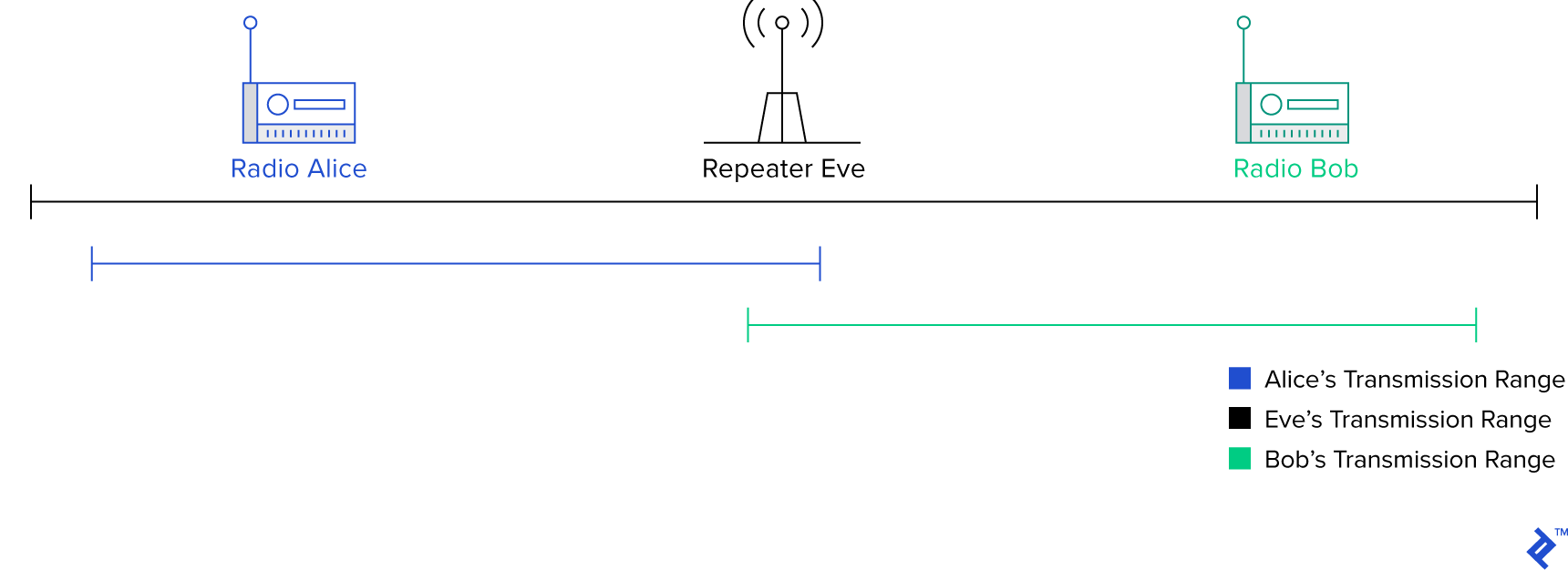
A repeater is a device that, well, repeats what it hears. It parrots what it hears on one frequency out on another frequency. The purpose of a repeater is to extend the range of other radios. It’s usually placed in a central place and very high up to give it a clear line-of-sight to area it covers. It may also output a large amount of power so that radios very far away can hear it as well. In the illustration above, we see visually how a repeater can help two small hand-held radios talk to each other over large distances. This is exactly how the Lahore repeater operates, except with more power.
The Lahore repeater operates at a frequency of 147.360 MHz*. Before you tune to that frequency, set your modulation selector to narrow band frequency modulation (NBFM/NFM), we’ll learn more about how this works later. At that frequency, you’ll hear a series of tones every five minutes. I recorded one of these for you here:
What are these tones, exactly? A look at the waveform will give us a clue.

If you haven’t caught on already on already, this is Morse code. Since this waveform is a representation of amplitude and time, the short beeps are dots and the long beeps are dashes. The audio, therefore, is signalling .-.. … .-. which decodes to LHR, the city abbreviation for Lahore. This tells you that the repeater is online, you’re tuned to the right frequency, and that you’re listening to the Lahore repeater.
While I was waiting, I asked my friend and licensed ham operator Badar Jamal, AP2BDR, the head of the PARS Lahore chapter, to have a quick conversation with me while I was tuned into the Lahore repeater. I have special authorization by the Pakistan Telecommunication Authority to operate a radio under the supervision of a licensed operator like AP2BDR. The conversation took place at a particularly bad time when the spectrum was very polluted, so there is noise. Also, despite my best efforts to put some distance between me and the RTL-SDR, my transmissions seem to overpower the device at some points, but here is the conversation below. I operate under an extension of PARS’ call-sign as AP2ARS/November.
And that’s how to listen in on a ham radio conversation between two licensed operators on a repeater. The process would be the same If they were transmitting without a repeater because the RTL-SDR does not transmit. The setup is, however, a bit more involved for transmission equipment since they have to transmit at a different frequency than at which they receive. If you’re like me though, this left you with more questions than answers. I’ll explain the science behind this in the next section.
Receiving Pictures from a Spaceship: SSTV Events from the International Space Station
The International Space Station (ISS) is a large artificial satellite orbiting the Earth. It is a space environment research laboratory jointly owned by five different space agencies: NASA (United States), Roscosmos (Russia), JAXA (Japan), ESA (Europe), and CSA (Canada) through a set of complex agreements and treaties. Since the international space station is a spacecraft, operated by a crew, it is technically a spaceship, and since it orbits the earth, it is also a satellite.
The ISS runs an amateur-satellite service under the Amateur Radio on the International Space Station or ARISS program. This service lets you contact the ISS where you can talk to amateur radio astronauts, but every now and then ARISS runs special slow scan television (SSTV) events where it broadcasts images over 145.8 MHz in narrow-band FM mode. One such event occurred between August 1-4, 2019, called the ARISS Garriott memorial SSTV activity. The event “celebrate[d] the life and accomplishments of astronaut, scientist and ham radio pioneer Owen Garriott with a commemorative SSTV event featuring images from Garriott’s work with ham radio during his missions in space.” He was the first ham to operate from space.
For this event, I set my dipole and my RTL-SDR up on the roof. The signal was incredibly weak, though, so using my RTL-SDR, I only managed to get a partial image during an exceptionally strong pass. I used alternative equipment for the rest of the event. However, other PARS members have had more success with RTL-SDRs and a self-made antenna using copper-tubing and coaxial cable. The process for listening to the signal was very similar to the previous one except for one additional step: accounting for the Doppler effect.
Noun: Doppler effect
an increase (or decrease) in the frequency of sound, light, or other waves as the source and observer move towards (or away from) each other. The effect causes the sudden change in pitch noticeable in a passing siren, as well as the red shift seen by astronomers.
The Doppler effect, or Doppler shift, is the apparent change in frequency as the emitter moves closer. Let’s think about an ambulance siren. As it’s coming towards us, it’s high in pitch, but when it passes us, it does this weird thing where the sound suddenly changes and becomes lower in pitch. As a child, I always thought that was weird: Why did ambulance drivers do that to me? How did they know they were passing me when I was indoors? Turns out, it happens to everyone, and not just for sound. The Doppler effect is apparent in all waves, including radio and light. Blueshift is when stars look blue to us, a higher wave frequency, as they come towards the earth, and redshift is when they appear red, a lower frequency, as they move away. For a demonstration, I recommend this excellent video.
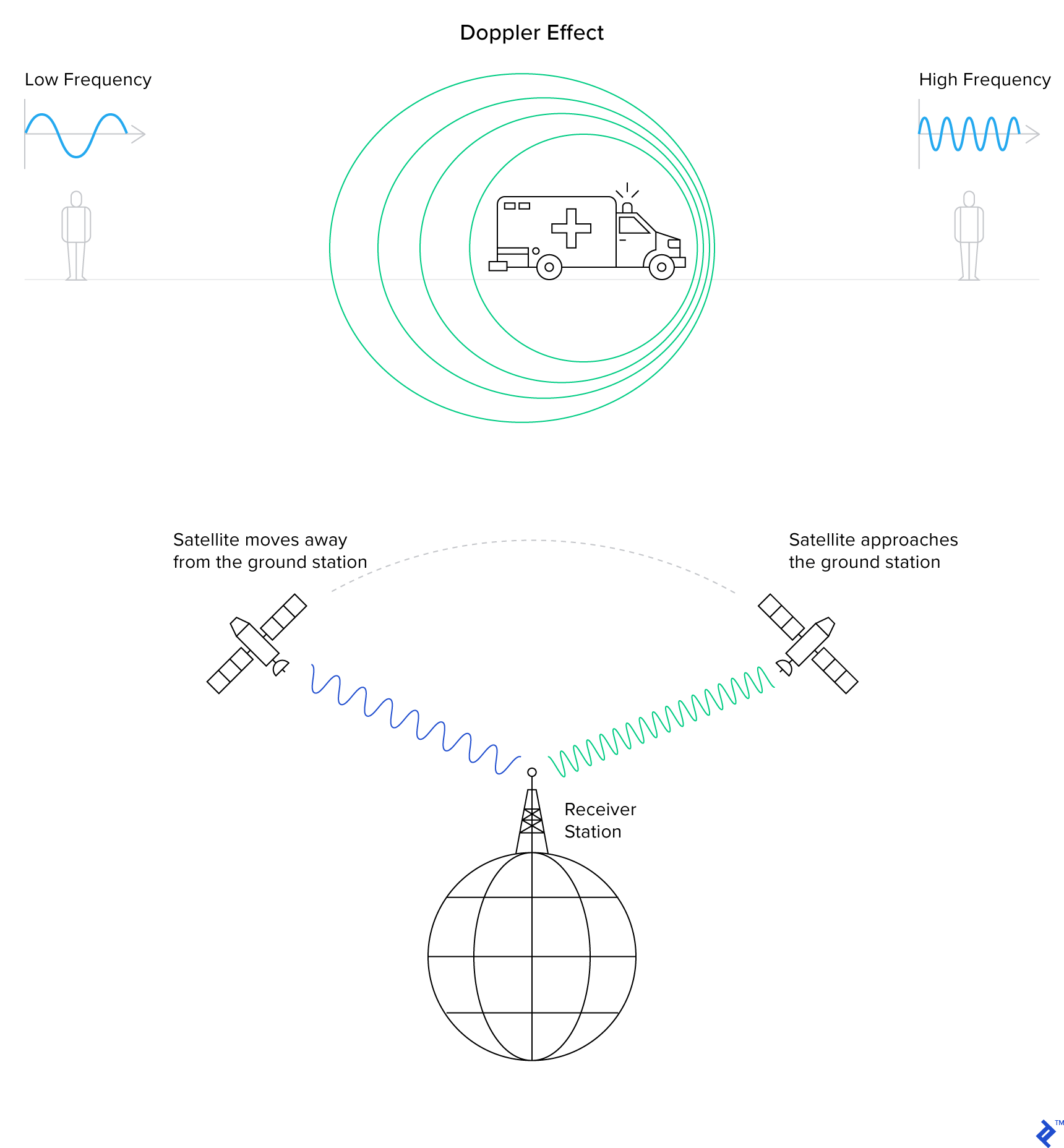
The Doppler shift manifests in satellites’ radio communications as an increase in pitch as the satellite moves towards you, and a sudden decrease as it moves away. On the SDR’s waterfall, it would appear like so:
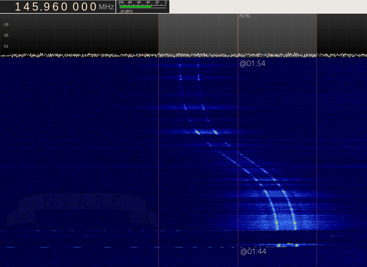
To compensate for the effect, I kept my radio to slightly above 145.8 MHz as the satellite arose, changed it down as the satellite reached its apex, and changed it further down when it set. Remember that while I did receive a partial, what I received was the following audio:
If you play this and run an SSTV decoder, like the Robo36 Android application, set to the PD120 mode, you should get the following image:
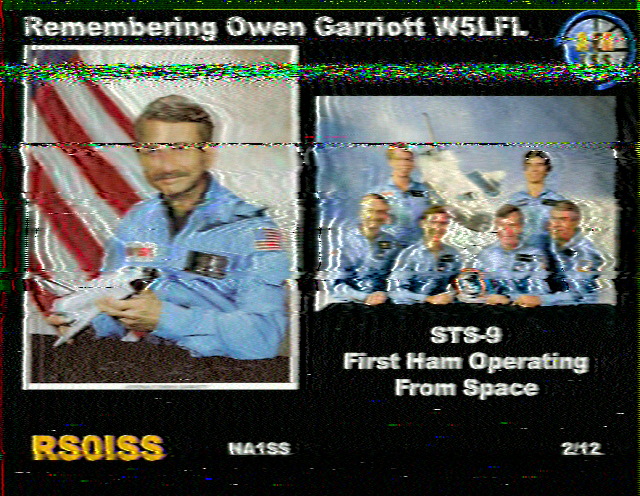
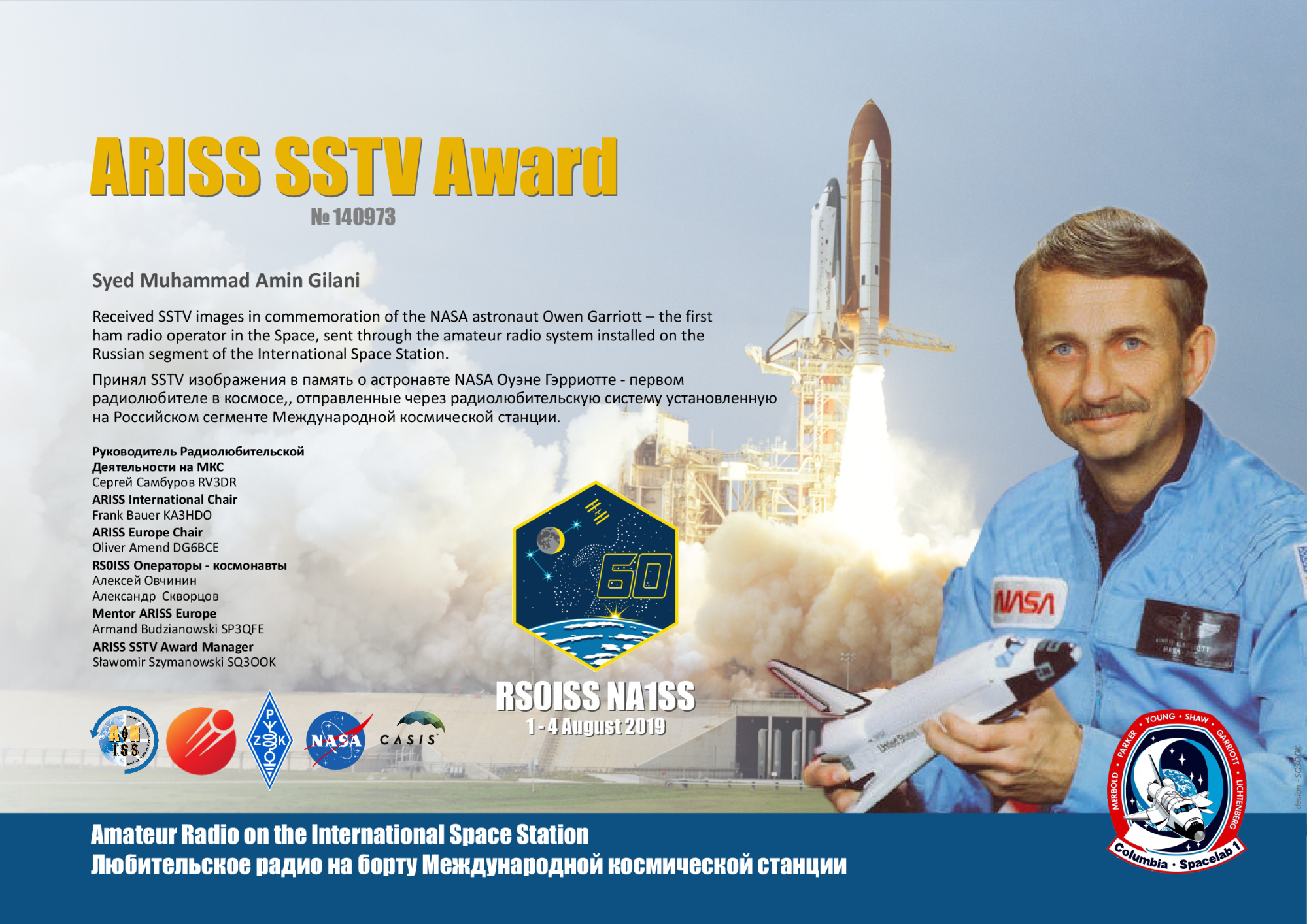
A photo tribute to Owen Garriot, the first ham operating from space. A genuine picture that I received directly from a spaceship. Using this picture, I claimed the ARISS SSTV Award.
Now let’s understand how radio technology works.
Demystifying Radio: The Science Behind the Magic
Alright, so, if you’re like me, you want to know more. How does a man speaking into a mic transmit invisible waves (what even are waves?) that are picked up (“picked up?”) by another magical box on the other end, and turned into sound? So many questions. Let’s begin. If, at first, some of these concepts don’t make sense, just bear with me until the end. Let’s discuss:
- Alternating current and how it makes magnetic waves
- The electromagnetic spectrum and radio frequencies
- How radio transceivers encode voice into and decode it from radio waves
Alternating Current and How It Makes Electromagnetic Waves
You’re likely aware of direct current, such as when you connect an LED to a 12V battery. This type of electricity outputs a constant voltage and is known as direct current (DC). If we were to plot the flow of current in the wire, we’d get something like this:

You’re probably familiar that current running through a wire causes a constant magnetic field in a circle around it. It looks a bit like this:
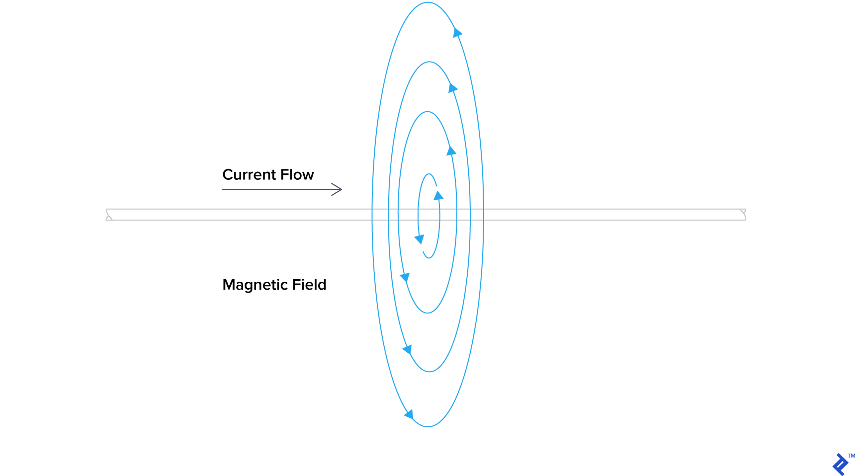
You can watch this effected demonstrated in this YouTube video.
DC does nothing for radio, though. We use its more interesting and deadly sibling: Alternating current (AC). AC is different from DC because instead of giving a constant voltage to the load, it alternates between giving and taking from it. AC is what you would get if you plugged into the main power at your house. In Pakistan, we get 230 volts alternating at 50 Hz or hertz (don’t worry about hertz for now), which is similar to the UK, however, in North America, you get 120 volts at 60 Hz. For simplicity, let’s assume it operates at 1 Hz. Here’s a graph of what my mains electricity would look like:
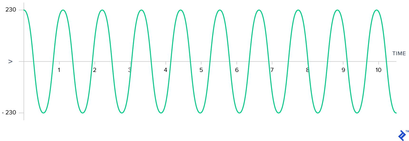
Now, here’s the interesting thing about AC: because of a changing current, we’re going to now cause a changing magnetic field around the wire. Changing magnetic fields have a special property, they induce currents in wires they pass through! This is called electromagnetic induction. All of radio is essentially electromagnetic radiation and induction by AC waves. Here’s a video of a man running a lightbulb off of dipole antenna, set to the same length as ours, and a signal in the 2 meter band:
The 2 meter band is, incidentally, the same band we heard AP2BDR and AP2AUM talking on, but what is this “band” that I speak of? Let’s see that next when we learn about radio frequencies.
Radio Frequencies and The Electromagnetic Spectrum
Electromagnetic (EM) radiation refers to the waves with electromagnetic components that propagate through space. In the video above, you saw a man emitting EM radiation with a dipole antenna, and then receiving it in one too. That’s exactly what we did in our experiment, although with less power. Radio waves are EM energy, but they aren’t the only thing that can be classified as such. Some other examples include light, ionizing radiations like X-rays and gamma rays. The difference between all these is the rate at which the EM oscillates. This is measured in both frequencies and wavelength, and sometimes, for amateur radio ranges, expressed as “meter bands.” Let’s take a look.

A cycle is the name given to a full oscillation, and is usually measured from peak to peak on the graph. The “frequency” of a wave is the number of cycles it goes through in a second, and the unit that denotes this is the hertz (Hz). In the diagram above, we measure a frequency of 1 cycle per second, or 1 Hz. This means that the AC wave oscillates, between giving and taking current, 1 time a second.
To understand wavelength, let’s visually imagine what our AC current would look like in a wire. Let’s imagine time stops, and we’re looking at an unknown AC current running through a wire. The high peaks are where the wire is positively polarized, the shallow valleys are where the wire is negatively polarized.

Looking at the wire visually, can you measure the length of a cycle in meters? Remember that a cycle is measured from peak to peak. When you have the answer, read ahead.
What you’ve just measured is the wavelength of a signal in a wire. The relationship between the wavelength of a signal and its frequency
$ \lambda = \frac{c}{f} \times VF $
Where $f$ is the frequency of the wave in Hz, $c$ is the speed of light constant expressed in meters per second, $\lambda$ is the wavelength meters, and $VF$ is velocity factor.
The $VF$ is given by the equation:
$ VF = v/c $
Where $v$ is the speed at which the signal propagates through the material.
For now, let’s assume signals will propagate through all material at $c$, making $v = c$, $VF = 1$, and we can simplify our equation for the wavelength to become:
$ \lambda = \frac{c}{f} $
You will encounter this simplified equation in a lot of places, but understand that it is only true for EM in a vacuum.
When we run an AC current through a perfect antenna, it radiates EM energy very efficiently. Here’s a visualization:
Notice how the EM radiation oscillates at precisely the same frequency as the AC current applied to the antenna? This is why a 450 hertz AC current fed to an antenna will radiate a 450 hertz signal radio signal.
In our experiment above, we heard AP2BDR and AP2AUM talk at 147.360 MHz*, that’s megahertz, or 147,360,000 hertz*. The wavelength for that frequency is 2.03 meters (79.92 inches). This brings us to our last approximation: meter bands.
Meter bands are just estimations of wavelengths. If you tell an amateur radio operator that you use the 2 meter band, they’ll take it to mean the frequencies that are approximately 2 meters in wavelength.
The electromagnetic spectrum refers to the range of frequencies and their classifications. Broadly speaking, there are 3 major categories: radio waves, light, and ionizing radiation, but these three phrases don’t convey the depth of the spectrum itself.
According to the ITU, radio waves start at the extremely low frequency (ELF) range, beginning at 3 Hz, and end at the extremely high frequency range, ending at 300 GHz. After this frequency, EM radiation becomes light, a little further, it becomes visible light, a little further beyond that, it starts becoming dangerous in the form of ionizing radiation.
How Radio Transceivers Encode and Decode Voice Data From Radio Waves
“A trans—what, now?” I hear you ask.
A transceiver is simply a device that can both transmit and receive radio signals. We don’t necessarily need both parties to have transceivers; a radio message can be sent if one person only has a receiver.
There are many signal encoding and decoding schemes, but for now, we’ll only discuss the two primary ones, one of which we used in the experiment above: amplitude modulation (AM) and frequency modulation (FM). If you’ve played with your car stereo for a while, the terms AM and FM are probably very familiar to you. Let’s look at exactly how they work.
First, let’s introduce two waveforms: a carrier wave, and an information signal that we plan to encode. The carrier wave is just a plain wave signal oscillating at a particular frequency, in our recording, much like the illustration, our carrier wave was a sinusoidal wave (smooth rising and falling shape) at a frequency of 147.360 MHz*. The information signal, is the data you want to encode, and in our experiment, it was the audio of the conversation between AP2BDR and AP2AUM.
In AM, the signal is encoded into the carrier wave by modulating the amplitude of the wave itself, meaning the carrier wave grows taller, but remains at the same frequency. In FM, however, signal is encoded into the carrier wave by modulating the frequency, meaning the carrier wave stays the same height, but the frequency varies a little bit.
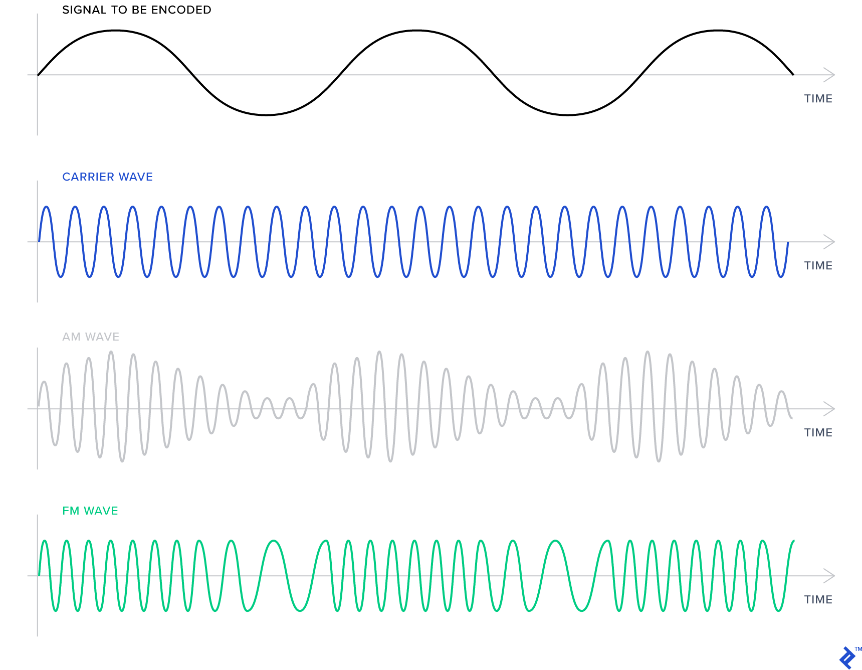
In our conversation, we used FM. FM usually results in clearer audio, and is more resistant to noise or distortion than AM, since distortion manifests as a change in amplitude. However, FM comes at the cost of using a range of frequencies rather than a specific frequency. How wide the range of frequencies is depends on your filter. In our example, we used narrow-band FM (NBFM); however, commercial radio stations use wide-band FM (WBFM). This makes the station sound richer and more resistant to distortion but requires a larger range of frequencies.
Conclusion
We’ve learned how radios work and some radio regulations, we set up a receiving dipole and explored the spectrum using a software defined radio, and we learned some basic physics behind radio waves as well as the fundamental methods of encoding and decoding the signal. Radio may seem like magic, and personally I still think it is, but it is quite a remarkable piece of technology. In a later article, I may discuss GNURadio and how it’s possible to emulate radio functionality in software.
I hope you’re interested in learning more about radio. Using your SDR, you can explore the signals your own devices produce, like the signals from your car’s key fob or from a wireless doorbell. Just remember to ensure that you carry out your experiments within the confines of the law. And if you decide to become a ham radio operator, you may start transmitting and having conversations of your own! In Pakistan, it’s legal to transmit from a radio station operated by a licensed ham, and under their supervision, if they are training you. I recommend you join PARS or your local amateur radio association for more information.
The best resource on amateur radio I’ve found is the ARRL Handbook for Radio Communications. It came highly recommended, and while the content in the book is incredibly technical at first glance, after a few reads, it starts making sense. It is an invaluable resource, and I find myself referring back to it frequently. However, it’s a paid book, but if you’re looking for something to start immediately, read the first five chapters of Wireless Networking in the Developing World, a free (as in libre) book and (gratis) ebook which cover the material I discussed in more detail.
*Note: PARS requested that I not publish real figures online. These are technically accurate examples, but the real ones are only available to PARS members.
Further Reading on the Toptal Blog:
- How does Shazam work? Music Recognition Algorithms, Fingerprinting, and Processing
- MIDI Tutorial: Creating Browser-Based Audio Applications Controlled by MIDI Hardware
- The Ultimate Guide to Building a WordPress Plugin
- After All These Years, the World Is Still Powered by C Programming
- How to Create Exclusive Custom Taxonomies in WordPress
Understanding the basics
What is software-defined radio used for?
Software-defined radio can be used for all traditional radio applications, but much more flexibly. This allows for the prototyping and development of next-generation radio applications. In this article, though, we use an RTL-SDR for simply receiving narrow-band FM signals.
How does software-defined radio work?
A software-defined radio works by implementing traditionally hardware components in software on a personal computer or embedded system.
What is a waveform in software-defined radio?
A waveform is a representation of a wave over a time period. In software-defined radio, it is the same as a waveform in regular radio. It can be used to represent the sound being modulated or demodulated, the signal being transmitted, radiated, or received, or any other waves in the process.
What is SDR in ham radio?
SDR can be used in ham radio like any other radio application. Amateur radio is a hobby about exploration, and so hams can use the SDR as a receiver, or as a transmitter. They can even use it to create completely new radio applications.
What is RTL in RTL-SDR?
RTL is short for RTL2832U. The Realtek RTL2832U chipset was a popular choice for digital video broadcast (DVB-T) receivers, whose original purpose was to receive video. It was discovered that these could be hacked and turned into wideband SDR receivers. These devices have come to be known as the RTL-SDR.
Can you transmit with SDR?
It depends on the SDR. If you have the right hardware, yes you can, but not with the RTL-SDR. Some transmission capable SDRs include the HackRF, PlutoSDR, LimeSDR, LimeSDR Mini, and more.
Lahore, Punjab, Pakistan
Member since January 27, 2017
About the author
Amin is a Ruby Association certified Gold Ruby Programmer who is passionate about learning new applications for technology.
